|
NimbRo ROS Soccer Package
|
|
NimbRo ROS Soccer Package
|
Namespaces | |
| behaviourcontrol | |
| This namespace defines everything that is required for the Behaviour Control Framework. | |
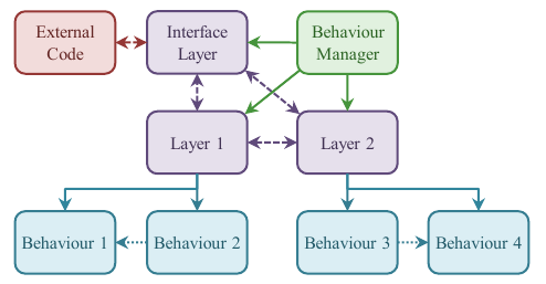
The Behaviour Control Framework (BC Framework) is a generic platform independent C++ framework designed for behaviour control on robotic platforms. It is intended for the implementation of mid- to high complexity agent behaviours. The main idea behind the framework is to separate the control task into a pool of independent behaviours, partitioned into so-called behaviour layers, where each behaviour can be defined to inhibit any number of other behaviours from within the same layer. The layers are generally organised in a total order of decreasing abstraction and resolution, and share information via virtual actuators and sensors, controlled by corresponding actuator and sensor managers. A parent behaviour manager links all of the layers together and implements a step routine that controls the execution of the entire structure. The layers are executed in a user-defined order, generally corresponding to the total order from highest level of abstraction to lowest level of abstraction. A key feature of the BC Framework is that multiple behaviours can concurrently be activated in each layer. An overview of the BC Framework architecture is shown in the following diagram.
The BC Framework has been developed as a solution to the behaviour control problem that is more powerful than the State Controller Library for large and complex systems. Being suitable for use in all application sizes down to the simplest of controllers is not a requirement of this framework, as it is for the State Controller Library. As such the "target markets" of the two behaviour frameworks intersect, but the frameworks do not preempt each other. The focus of the BC Framework was on the creation of a platform that would facilitate the implementation of complex behavior controllers, suitable for use on the NimbRo-OP and for humanoid soccer (i.e. the NimbRo-OP Soccer Behaviour package). Performance and efficiency of the framework were of high consideration, as well as its integrability and interoperability with the remaining code. Usability, structure and customizability were also of key concern.
The Behaviour Control Framework and the State Controller Library are detailed in the following paper.
P. Allgeuer and S. Behnke, "Hierarchical and State-based Architectures for Robot Behavior Planning and Control," in Proceedings of the 8th Workshop on Humanoid Soccer Robots, IEEE-RAS Int. Conference on Humanoid Robots, Atlanta, USA, 2013.
You are kindly asked to cite this paper if you use this framework for academic work.
@INPROCEEDINGS{Allgeuer2013,
  author = {Philipp Allgeuer and Sven Behnke},
  title = {Hierarchical and State-based Architectures for Robot Behavior Planning and Control},
  booktitle = {Proceedings of the 8th Workshop on Humanoid Soccer Robots, IEEE-RAS Int. Conference on Humanoid Robots},
  year = {2013},
  address = {Atlanta, USA}
}
This library depends on the following external libraries (to avoid requiring C++11):
For more information, or to download the Boost Libraries, please refer to http://www.boost.org/.
The inhibitions between the behaviours of each behaviour layer are processed at the beginning of program execution, before the step routine is first called. At this point the inhibition definitions are compiled into a directed acyclic graph, referred to as the inhibition tree. It is strictly an error if a cycle in the inhibitions exist, as this would lead to unpredictable behaviour activations. Individual inhibition definitions can be specified as being either chaining or non-chaining. The chaining inhibitions are considered to act transitively with other chaining inhibitions, leading to additional implicitly defined inhibitions, while the non-chaining inhibitions do not. Once the inhibition tree has been established, the behaviours are topologically sorted with respect to it, in order to ensure that the resolution of the inhibitions at runtime is unambiguous.
At the beginning of every step, each behaviour in a layer is queried for its requested activation level. This is a real number on the unit interval and is a measure of how relevant a behaviour is to the perceived current situation. A value of 1.0 corresponds to a request for complete activation, while 0.0 corresponds to complete deactivation. The activation levels are used for two purposes, to evaluate which behaviour(s) are active in a layer at any one time, and to aggregate actuator values, as discussed in the following section. The behaviours are traversed in their topological order, and the respective inhibitions are applied multiplicatively. This means for example that if a behaviour with an activation level of 0.7 inhibits another behaviour of activation level 0.9, then the latter will have its activation level reduced through multiplication by 1 - 0.7 = 0.3. In by far the most common case, this means that a behaviour with an activation level of 1.0 completely prevents all of the behaviours it inhibits from executing. In this way, the requested activation levels are refined into a set of true activation levels.
As the hierarchy of behaviour layers are executed during a step from the top down, it is generally required that the output of higher order planning in the upper layers is made available to the lower layers. This is done using a network of virtual actuators and sensors. Each layer receives data through its sensors and delivers its output via its actuators. This is a single sender multiple receiver arrangement, where multiple sensors in multiple layers can request to receive the data from the same actuator. Actuators are uniquely identified by name, and support the use of arbitrary data types for information exchange. If the data type numerically supports it, an actuator can be made to be aggregatable. This allows multiple concurrently active behaviours to write to the same actuator. The output that is read by the corresponding sensors is then calculated as the average of the written values, weighted by activation level. This allows competing behaviours to have combined influence on an agent, provided this effect is desired.
In addition to the transfer of data between layers, there is usually also a need to exchange data with external sources. Most commonly this is in the form of real-world sensory perceptions and motion commands. The concept of interface layers exists for this purpose. From the perspective of the behaviour manager this is simply a normal behaviour layer with a slightly modified time of callback execution. This is necessary so that the external data can be sent and received at the appropriate times within a step. A ROS interface layer has been implemented as part of the NimbRo-OP Soccer Behaviour package, which is based on this framework. This allows communication of the behaviours node with the other nodes in the system via the inbuilt ROS topics and services. Interface layers also make it possible to split up a behaviour control system over process boundaries, meaning that multiple loop rates can be used. For example, higher-level layers can be made to execute at a slower rate than the more time-critical lower-level layers.
For a conceptual description of the initialisation order of a behaviour manager, refer to the initialiseArchitecture() function. For a description of the execution order, refer to the step() function. Referring to the source code of each of these functions also greatly helps clarify the initialisation and step processes (see behaviour_manager.cpp).
Now suppose that we have the following behaviour architecture using the BC Framework (note that this is the automatically generated output from the BehaviourManager::toString() function):
Defined Behaviour Architecture
==============================
The MyM behaviour manager contains:
(0) RosIL (Interface)
(1) MyL1
  (0) MyB2
  (1) MyB1
(2) MyL2
  (0) MyB3
  (1) MyB4

RosIL Layer
===========
RosIL has a sensor manager with the following sensors:
(0) MyL2/mode
(1) MyL2/count
(2) MyL2/target
RosIL has an actuator manager with the following actuators:
(0) ROS/mode
(1) ROS/targetX
(2) ROS/targetY

MyL1 Layer
==========
MyL1 has a sensor manager with the following sensors:
(0) ROS/mode
(1) ROS/targetX
(2) ROS/targetY
MyL1 has an actuator manager with the following actuators:
(0) MyL1/mode
(1) MyL1/xgoal
(2) MyL1/vgoal

MyL2 Layer
==========
MyL2 has a sensor manager with the following sensors:
(0) MyL1/mode
(1) MyL1/xgoal
(2) MyL1/vgoal
MyL2 has an actuator manager with the following actuators:
(0) MyL2/mode
(1) MyL2/count
(2) MyL2/target
Then the initialisation order should look like this (this is also automatically generated program output):
Initialising the architecture...
Initialising class MyM
Initialising class RosIL
Initialising class RosILSM
Initialising class RosILAM
Initialising class MyL1
Initialising class MyL1SM
Initialising class MyL1AM
Initialising class MyB2
Initialising class MyB1
Initialising class MyL2
Initialising class MyL2SM
Initialising class MyL2AM
Initialising class MyB3
Initialising class MyB4
Initialisation succeeded!
Now if we simulate some activation levels and actuator writes, and execute two steps of the behaviour manager we can get something like this (note that for clarity reasons, not all callback types are shown here, e.g. the actuator manager update callbacks are not shown):
Calling the step function...
  Pre-step callback in manager 'MyM'
  User-updating layer 'RosIL'
  Read 4 from the 'mode_in' ROS topic
  Read -1.5 from the 'targetX' ROS topic
  Read 5.12 from the 'targetY' ROS topic
  User-updating layer 'MyL1'
  User-updating behaviour 'MyB2'
  User-updating behaviour 'MyB1'
  Executing behaviour 'MyB2'
  Executing behaviour 'MyB1'
  Post-executing layer 'MyL1'
  User-updating layer 'MyL2'
  User-updating behaviour 'MyB3'
  User-updating behaviour 'MyB4'
  Executing behaviour 'MyB3'
  Executing behaviour 'MyB4'
  Post-executing layer 'MyL2'
  Writing 1 to the 'mode_out' ROS topic
  Writing 28 to the 'count' ROS topic
  Writing 183 to the 'target' ROS topic
  Post-executing layer 'RosIL'
  Post-step callback in manager 'MyM'
Calling the step function...
  Pre-step callback in manager 'MyM'
  User-updating layer 'RosIL'
  Read 8 from the 'mode_in' ROS topic
  Read -3 from the 'targetX' ROS topic
  Read 10.24 from the 'targetY' ROS topic
  User-updating layer 'MyL1'
  User-updating behaviour 'MyB2'
  User-updating behaviour 'MyB1'
  Executing behaviour 'MyB2'
  Executing behaviour 'MyB1'
  Post-executing layer 'MyL1'
  User-updating layer 'MyL2'
  User-updating behaviour 'MyB3'
  User-updating behaviour 'MyB4'
  Executing behaviour 'MyB3'
  Executing behaviour 'MyB4'
  Post-executing layer 'MyL2'
  Writing 1 to the 'mode_out' ROS topic
  Writing 44 to the 'count' ROS topic
  Writing 187 to the 'target' ROS topic
  Post-executing layer 'RosIL'
  Post-step callback in manager 'MyM'
Done!
No inhibitions were implemented in this sample architecture, but if for example MyB3 were to inhibit MyB4, the inhibited() callback of the MyB4 behaviour would execute instead of the execute() callback whenever MyB3 returns that it should be activated.
The following notes describe certain aspects of the framework in more detail.
LBase or MBase or similar pointer into the Behaviour or BehaviourLayer or Actuator or Sensor class constructors unavoidably results in a segmentation fault as the dereferencing of these pointers needs to happen in the initialisation list... so don't do it!init() functions you can safely assume that each of the parents exists and is initialised. For example, a behaviour can assume that the behaviour layer and behaviour manager have already been initialised, but should not rely on any particular initialisation order between sibling behaviours.A (relatively) minimal example of how to use this framework is shown below. For brevity reasons, this example only defines a single layer, and with only a single child behaviour. In real applications of this framework, naturally an arbitrary number of child layers and behaviours is possible, and it is recommended that each layer and behaviour is separated into its own header/source file pair. This is beneficial for source control (e.g. git) and collaboration between multiple programmers. Also in the following example, only a single actuator and sensor are implemented. Normally these would be used to pass data between layers, but as there is only a single layer, they have been bound to each other instead. This has the effect of making the output from one step available as an input to the next step. This would normally be achieved using layer-shared variables, unless the use of aggregation is important. The behaviour in this example simply keeps incrementing four variables from throughout the architecture. To do something more useful, such as sending actuator commands in the case of a robot, it is possible to include the code directly in the behaviour. It would be highly recommended however to implement an interface layer and make use of the sensor and actuator framework. This helps to avoid possibly breaking the architecture's intended data flow model, allows the use of aggregation, and is more modular.
See test/test_behaviour_control.h and test/test_behaviour_control.cpp for more examples of how to define and run behaviours, layers and managers.
See behaviour_control.h and behaviour_control.cpp (and the therein included header files) for the framework source code.
 1.8.6
1.8.6 
